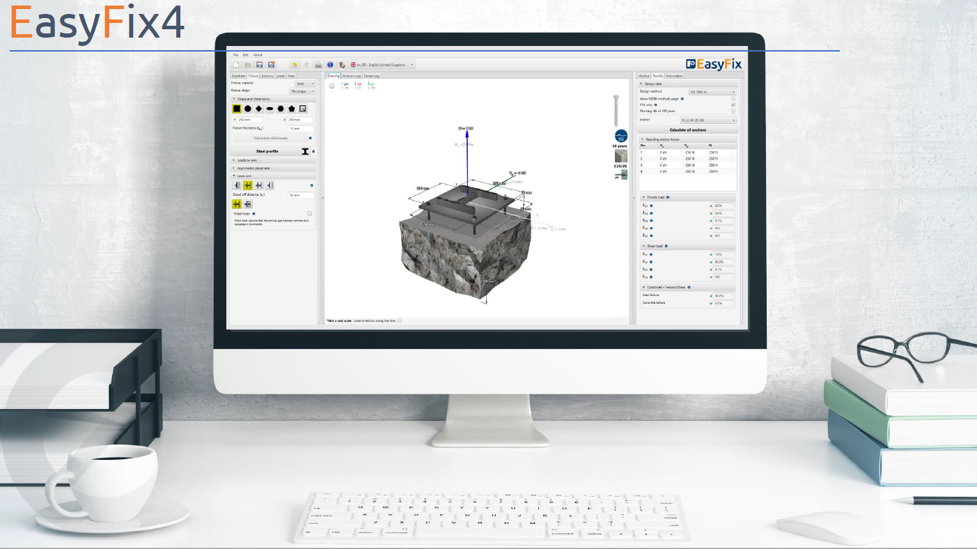
The «Сoncrete» сalculation is dedicated to the selection of anchors for the concrete, in accordance with the following recommendations: EN 1992-4, ETAG 001, ACI 318-11, AS 5216:2018, CТО 36554501-048, ETAG, FIB SAG4 06, CEN/TS 1992-4-4. The given module allows you to choose the shape of the plate, the number of anchors and their displacement in relation to the fixed element. Additionally, the user can introduce not only static loads, seismic loads, but also loads under the action of fire. After introducing the loads, the optimization function allows you to quickly select the appropriate type and size of the anchor, and in the event of any design changes, change the connection arrangement along with the change of the anchor type.
Lever arm
Lever arm – distance between the shear force and the surface of the concrete substrate. It is used to calculate the shear anchors when an additional from the shear force should be taken into account.
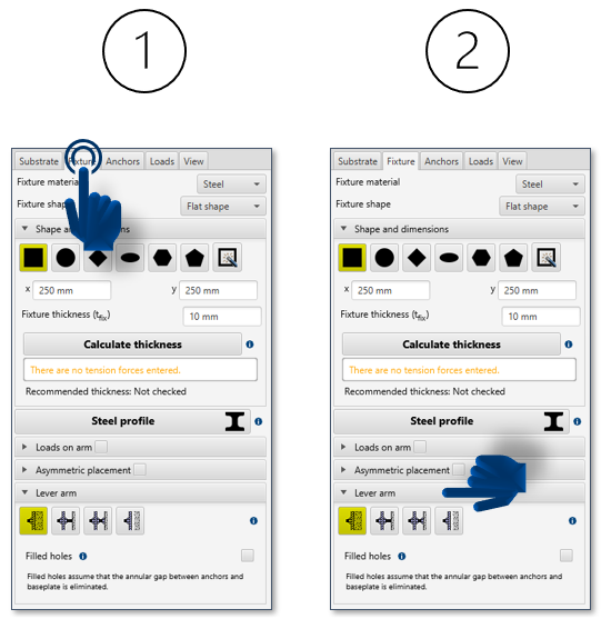
The basis for the calculations is:
- Selection of the type of lever arm
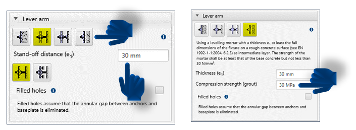
- Entering the lever arm length or the grout strength in the case of grouting
The design bending moment acting on the connector is calculated according to the following formula:
![]()
where:
VEd – shear load acting on the connector in question;
la – the factor determining the distance between the load and the shear force and the determination of the fixing stiffener distance, is calculated according to the following formula:
la = a3 + e1
a3 = 0,5 · dnom
a3= 0 – of the nut and washer are completely screwed to the concrete surface or the surface of the anchor channel, or if a grout with a strength ≥ 30 N/mm2 and thickness is used tgrout ≥ d / 2
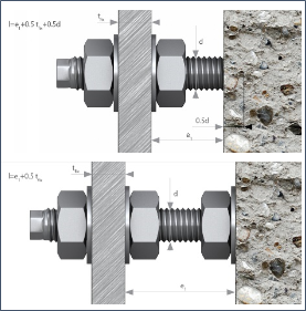
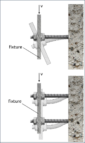
Lever arm
Lever arm with an additional nut and washer to secure local concrete crushing
e1 – distance between the shear load and the surface of the concrete substrate;
aM – connector stiffening factor on the base plate;
aM = 1,0 – without stiffening;
aM = 2,0 – total stiffening;
aM = 1,0 – free rotation of the base plate
aM = 2,0 – base plate cannot be rotated
We do not include the distance fixing in the following cases:
- If the base plate is made of steel and is in contact with the abutment for at least 0,5 · tfix;
- The base plate is fixed:
- directly into concrete without an intermediate layer; or
- with the use of grout as an intermediate layer, with tgrout ≤ 0,5d made at least under the entire base plate on the rough concrete surface (the strength of the mortar should be at least equal to the strength of the concrete in the substrate, but not less than 30 N / mm2.
After selecting a spacer in the program, the program selects the appropriate solution, taking into account the length of the spacer and the shear force. In the event of design changes, the user will be able to easily enter other parameters of the spacer assembly.
Do you need design support ?
We will help! – Rawlplug Technical Helpdesk
Find out more at rawlplug.com


Comment section
Share this article: